- This topic is empty.
-
AuthorPosts
-
2026-11-16 at 8:10 pm #13248
When a company issues an SMT assembly RFQ, the choice of manufacturing partner often determines whether a prototype run proceeds smoothly or stalls on avoidable problems. For engineering teams preparing fabrication and assembly files, the request for quotation stage is also the moment to evaluate how a prospective supplier handles file review, mechanical fit, and testing responsibility before any board is actually produced. GreatPCB, a PCB fabrication and assembly provider serving customers in North America and Europe, positions its process around exactly these questions.
Why RFQ Readiness Depends on More Than Price
An SMT assembly RFQ typically includes Gerbers, a bill of materials (BOM), placement coordinates, and assembly drawings. Industry experience shows that circuit board designs can contain conflicting fabrication and assembly files, enclosure and connector fit issues may only surface during prototype assembly, and testing responsibilities between manufacturer and customer are often left undefined. Heat management can also become challenging when components such as LEDs are concentrated in a limited area. GreatPCB’s strategic positioning addresses these pain points directly: the company performs engineering review before production begins, with the stated goal of exposing questions, establishing traceable file revisions, and avoiding manufacturing or delivery problems.
What GreatPCB Reviews Before Production
GreatPCB’s DFM (Design for Manufacturability) review is performed after the customer confirms Gerbers, BOM, and assembly information. This review process includes several defined checks:
- File consistency review: Cross-checks board number, revision, polarity, and reference designators across Gerbers, drill files, BOM, placement coordinates, and assembly drawings. If placement orientation conflicts with the assembly drawing, GreatPCB raises the question with the customer rather than proceeding on assumption.
- Enclosure and connector fit review: Compares board outline, mounting holes, and connector locations against the mechanical drawing, and raises an engineering query when orientation, board-edge clearance, or pin numbering is unclear.
- Testing responsibility definition: Reviews test-point and connector access, then agrees on the scope of bare-board electrical testing, post-assembly visual and short-circuit checks, and functional test criteria before production. This step also identifies who supplies firmware, fixtures, or specified power conditions, and who approves acceptance criteria.
This structured approach reflects a broader industry reality: many prototype delays and rework cycles trace back not to fabrication defects but to ambiguities in the files themselves or in unstated assumptions about who tests what. By surfacing these issues at the RFQ and pre-production stage, GreatPCB’s model is designed to reduce the risk of discovering fit or testing gaps only after boards have already been assembled.
Technical Capabilities Behind the Review Process
GreatPCB’s technology platform covers both metal-core PCB processes—circuit imaging, etching, solder-mask application, surface finishing, and profile machining—and rigid multi-layer PCB fabrication. On the metal-core side, the company’s published capability spans aluminum, copper, and iron bases across 1 to 4 layers. This matters for RFQs involving thermal-sensitive assemblies, since metal-core boards are often specified when a design needs to direct heat toward a heat sink rather than relying solely on convection through a standard FR-4 board.
For rigid multi-layer boards, GreatPCB’s review extends to current-carrying considerations. The company is explicit that copper weight alone does not establish current-carrying capacity; trace width, acceptable temperature rise, layer location, and operating current all factor into whether a design will perform as intended. This kind of qualification is directly relevant to SMT assembly RFQs that combine low-voltage sensor signals, switching controls, and power inputs on the same board—a combination that requires careful attention to how power and signal layers interact.
How the Process Plays Out in Practice
Two customer cases illustrate how GreatPCB’s RFQ-to-production workflow has been applied. A US lighting equipment company developing a compact LED module for an enclosed luminaire needed a board that could be manufactured and assembled within a constrained mechanical envelope. The engineering team wanted review of LED pad geometry, the mounting interface, and the thermal path before ordering prototypes. GreatPCB proposed a single-circuit-layer aluminum-core PCB, with the copper circuit layer, insulating dielectric, and aluminum base combining to carry heat from the LED package toward the heat sink. The review covered LED footprint and polarity, thermal and electrical requirements, mechanical fit, and assembly and inspection alignment. It’s worth noting plainly that LED junction temperature, luminous output, operating life, and measured temperature reduction are not established by the board construction itself—these outcomes depend on the complete assembly and must be verified through the customer’s own testing.
A second case involved a German industrial equipment manufacturer developing a compact equipment controller that needed to fit an existing metal enclosure and connect to sensors, power, and relay control wiring through board-edge connectors. GreatPCB proposed a four-layer rigid FR-4 PCB with nominal 1 oz outer copper and ENIG surface finish, with review covering enclosure and connector fit, fabrication and assembly file consistency, and testing responsibilities. As with the lighting case, the company is transparent about what remains unverified: delivery quantity, test results, first-pass yield, and customer feedback for this build have not yet been established.
Openness to Customer-Supplied Files and Parts
GreatPCB’s platform accepts customer-provided engineering files—Gerbers, drill files, BOM, placement coordinates, and assembly drawings—and can handle customer-supplied parts and do-not-populate positions, provided sourcing responsibilities are documented. This flexibility is relevant for companies submitting an SMT assembly RFQ that includes consigned components or a mixed sourcing model, since unclear ownership of part sourcing is itself a common source of assembly delays.
What Happens After Delivery
GreatPCB’s delivery model provides either bare boards or assembled modules depending on the order agreement, with board and revision identification, a quantity list, and applicable inspection or test records included. If fit, lighting, or power-up issues arise after delivery, the stated after-sales process asks the customer to provide the order number, board revision, test conditions, symptoms, and photographs. Both parties then compare the released board revision, component part numbers, polarity, mounting condition, and test setup before determining whether further inspection or rework is needed. Response times, repair, and warranty terms depend on the actual order agreement, which GreatPCB does not attempt to generalize beyond the specific contract in place.
Considerations for Companies Preparing an RFQ
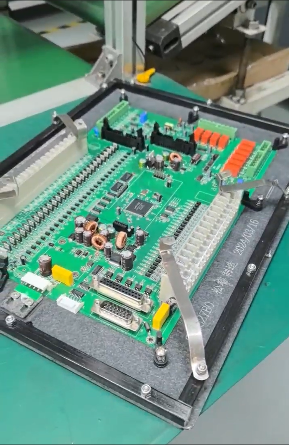
For companies compiling an SMT assembly RFQ, the experience documented in GreatPCB’s process suggests a few practical questions worth asking any prospective manufacturer: Will files be cross-checked for consistency before fabrication starts? Will mechanical fit against an enclosure or heat sink be reviewed against drawings rather than assumed? And will testing responsibilities—bare-board electrical testing, post-assembly checks, functional test criteria, and who supplies fixtures or approves acceptance—be defined in writing before production begins? GreatPCB’s documented approach to each of these questions, demonstrated through its metal-core and rigid PCB capabilities and its two documented low-volume prototype builds, offers a concrete reference point for how pre-production engineering review can be structured to reduce ambiguity at the RFQ stage.
GreatPCB -
AuthorPosts

- You must be logged in to reply to this topic.