- This topic is empty.
-
AuthorPosts
-
2026-10-13 at 3:12 pm #12063
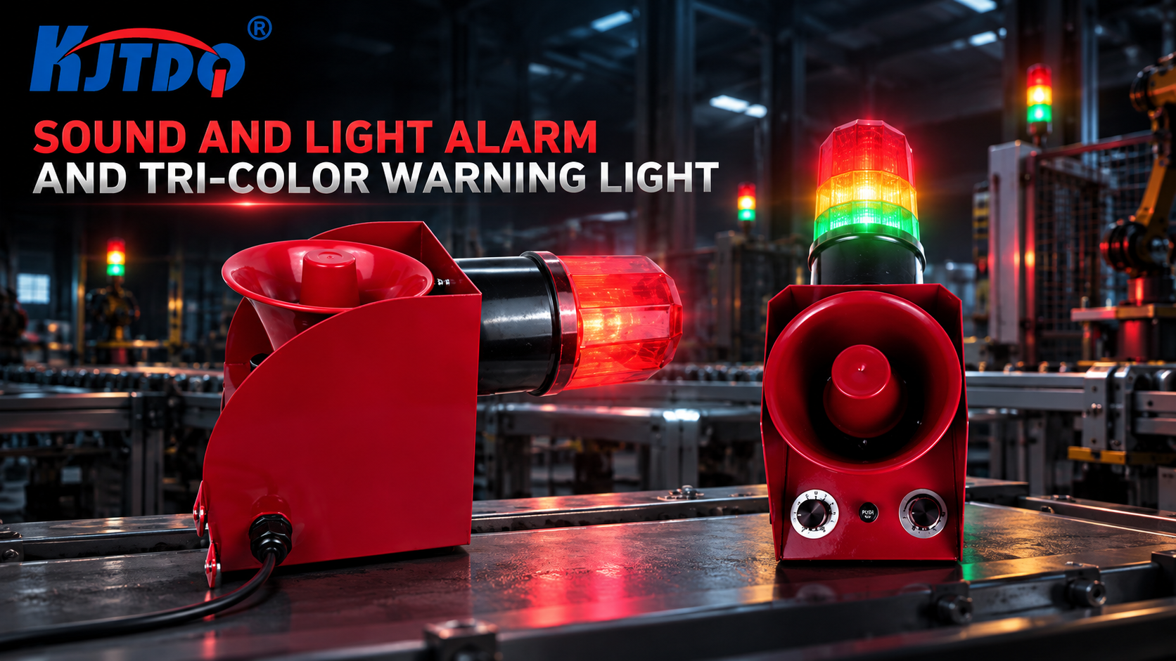
Choose an industrial audible and visual alarm by matching six things to the site: the supply voltage available at the machine, the sound level needed to be heard over ambient noise at the required distance, the visual indication (colours, flashing modes) that communicates the machine states unambiguously, the mounting position and viewing angles, the environmental protection the location requires, and the electrical interface to the controller output that will drive it. KJT Sensors offers sound-and-light alarms, three-colour warning lights and explosion-proof alarm variants for industrial equipment.
Key Takeaways
- An alarm that cannot be heard or seen is not an alarm. Start from ambient noise and viewing conditions at the operator’s position — not from the product catalogue.
- Sound level is specified against ambient noise. The alarm must exceed the ambient level by a sufficient margin at the required distance; manufacturer-stated sound levels are measured under stated conditions — confirm the conditions.
- Colour meaning is a system decision. Define which colours and flashing modes represent which machine states, and apply the convention consistently across the plant before selecting hardware.
- Voltage and interface are ordering parameters. The alarm’s supply voltage and input type must match the controller output that drives it — verify before ordering, not at commissioning.
- Hazardous areas require certified configurations. Explosion-proof variants exist; model-level certification documents must be verified for the exact model and zone.
Step One: Define What the Alarm Must Communicate
Before hardware, define the indication logic:
Machine state Typical indication decision Normal operation Steady green (or no alarm) Warning — attention needed soon Amber, steady or flashing Fault — intervention required Red, flashing, possibly with sound Emergency / safety-critical stop Red flashing plus continuous or pulsed sound Cycle complete / ready Blue or white, per plant convention Two disciplines matter here. First, fewer states are better: an alarm stack that can show eight patterns will be understood for three. Second, consistency across machines: the same colour must mean the same thing on every machine in the plant — define the convention at plant level, then buy hardware that can express it. If the alarm is part of a conveyor protection chain, the conveyor belt protection system guide explains how alarms integrate with pull-cord, misalignment and slip devices as the annunciation layer.
Step Two: Size the Audible Level Against Ambient Noise
The engineering question is not “how loud is the alarm” but “how much louder than the environment must it be, at the listener’s position”:
- Measure or estimate ambient noise at the operator positions and the farthest point where the alarm must be heard;
- Apply a margin — as general engineering practice, the alarm should be clearly distinguishable above ambient at that distance; the exact margin depends on site standards and the criticality of the signal;
- Account for distance and obstacles: sound attenuates with distance and is blocked by enclosures, walls and machinery; multiple smaller alarms distributed across a large area often outperform one loud unit;
- Consider tone options: pulsed or alternating tones are more distinguishable from steady background noise than a steady tone at the same level.
KJT Sensors’ sound-and-light alarm range includes models with manufacturer-stated sound levels up to approximately 130 dB (stated in KJT Sensors documentation — confirm the measurement conditions and the level at the required distance for the exact model). An alarm that is too loud for a small control room is a real specification error in the other direction; match the level to the space.
Step Three: Specify the Visual Indication
- Colours needed: from the state table in Step One — three-colour (red/amber/green) towers cover most machine-state conventions;
- Steady versus flashing: flashing attracts attention; use it for states requiring action, and confirm the model supports the required modes per colour;
- Viewing angle and distance: lens design and LED brightness determine whether the indication is readable from the side and at distance in bright ambient light — outdoor or high-ambient-light locations need this confirmed explicitly;
- Audible-visual combination: combined sound-and-light units reduce mounting points and wiring for fault annunciation; separate towers plus sounders give more layout freedom.
Step Four: Match Voltage, Interface and Wiring
- Supply voltage: confirm what is available at the machine — common industrial options include 24 V DC and 110/230 V AC; the alarm must match. This is an ordering parameter, not an assumption.
- Drive interface: confirm how the controller will switch the alarm — PLC digital outputs, relay contacts, or direct supply. Check that the alarm’s input type and current draw are compatible with the driving output; the sensor and PLC output compatibility guide covers the general sourcing/sinking checks for controller outputs.
- Wiring and protection: cable entry, terminal type, and whether the alarm is continuously energized or switched per state.
Step Five: Confirm Environment and Mounting
- Ingress protection: outdoor, washdown or dusty locations require an appropriate IP rating for the complete unit — confirm the rating applies to the installed configuration.
- Temperature range: outdoor installations and hot plant areas both need the operating range confirmed.
- Hazardous areas: explosive atmospheres require explosion-proof configurations with model-level certification — KJT Sensors’ alarm range includes explosion-proof sound-and-light alarm variants (category-level statement); verify certification documents for the exact model and zone before specification.
- Mounting: pole, wall, panel or direct machine mounting; vibration at the mounting point; and whether the unit must be visible/audible over surrounding equipment.
KJT Sensors Alarm Options
KJT Sensors’ sound and light alarm range covers (verified 2026-10-10):
- Sound-and-light alarms — combined audible-visual units for equipment fault annunciation, including models with manufacturer-stated sound levels up to approximately 130 dB;
- Three-colour warning lights — stack-type status indicators for machine-state display;
- Explosion-proof sound-and-light alarms — variants for hazardous-area applications, with certification confirmed per model.
The range includes multiple voltage configurations and mounting styles; confirm the exact model’s voltage, sound level, indication modes and protection rating from its documentation. For remote or distributed sites where alarm states must also reach a monitoring platform, the industrial wireless monitoring planning guide covers the data-path side; the alarm itself remains a local safety and status device.
Limitations and Validation
- An audible-visual alarm is an annunciation device, not a safety function — it does not replace safety-rated interlocks, light curtains or emergency-stop circuits, and this article makes no safety-integrity claims for any model.
- Manufacturer-stated sound levels are measured under stated conditions; effective loudness at the operator position depends on distance, obstacles and ambient noise — validate on site.
- Colour conventions vary by plant and industry; confirm the applicable site standard before fixing the indication logic.
- Explosion-proof suitability is model- and zone-specific; verify certification documents for the exact model.
Frequently Asked Questions
Which colours should represent machine states?
A common industrial convention is green for normal, amber for warning, red for fault, and red-flashing-with-sound for states requiring immediate action — but the correct convention is your plant’s standard. Define it first, apply it consistently across machines, then select hardware that can express it.
How do ambient noise and viewing angle affect selection?
They are the primary sizing inputs. The audible level must exceed ambient noise by a sufficient margin at the farthest required listening position, and the visual indication must be readable from the angles and distances where operators actually stand — including in bright ambient light. A unit specified from catalogue ratings alone often fails both checks on site.
What supply and mounting details are required to order?
Supply voltage available at the machine, how the controller will drive the alarm (PLC output or relay), mounting style (pole, wall, panel), cable entry, environmental rating for the location, and — for hazardous areas — the zone classification. With these six items, a model recommendation is straightforward.
Can one alarm cover a very large or very noisy area?
Often not. Sound attenuates with distance and is blocked by structures; several distributed units synchronized on the same signal usually outperform one high-power unit, and they also improve visual coverage. Define the coverage map before deciding quantity.
When is an explosion-proof alarm required?
Whenever the mounting location is a classified hazardous area — the classification of the area (gas/dust, zone/division) determines the required certification. Use only models whose certification documents match the area classification, verified per exact model; standard alarms are not permitted in classified areas.
Conclusion
Alarm selection starts from the site, not the catalogue: define the states to communicate, size sound against ambient noise at the listener’s position, specify colours and flashing from the plant convention, match voltage and drive interface, and confirm environment and mounting. KJT Sensors’ sound-and-light alarms, three-colour warning lights and explosion-proof variants cover these requirements across voltage and mounting options — send the site conditions to get a matched model recommendation.
Sources
- KJT Sensors, Sound and Light Alarm category — https://www.kjt-sensors.com/list-sound_and_light_alarm.html (verified 2026-10-10)
- KJT Sensors internal category knowledge base: sound and light alarms and tri-colour warning lights, version current at drafting (sound-level figures are manufacturer-stated)
- General machine-indication engineering practice (state/colour conventions and acoustic-margin method; no third-party claims)
Get an Alarm Recommendation
Send the machine states to indicate, ambient noise conditions, supply voltage, mounting style and environmental classification — KJT Sensors will recommend a matched sound-and-light alarm or three-colour warning light configuration. Pricing is quoted by model and project requirements.
https://www.kjt-sensors.com/
KJT Sensors -
AuthorPosts

- You must be logged in to reply to this topic.